Monday, December 28, 2015

Electronic pollution and E-Waste


Electronic Pollution:
In electronic industry fumes and gases are released during hand soldering/wave soldering/dip soldering, which are harmful to people as well as environment and the end products.
Government accords utmost importance to control environmental pollution.
India having acceded to the Montreal Protocol in September 1992, the production and use of Ozone Depleting Substances (ODS) like Chlorofluoro Carbon (CFC), Carbon Tetrachloride, Halogens and Methyl Chloroform etc.
What is E-waste?
E-waste consists of all waste from electronic and electrical appliances which have reached their end- of- life period or are no longer fit for their original intended use and are destined for recovery, recycling or disposal. It includes computer and its accessories monitors, printers, keyboards, central processing units; typewriters,
mobile phones and chargers, remotes, compact discs, headphones, batteries, LCD/Plasma TVs, air conditioners, refrigerators and other household  appliances.5

Pollutants in e-waste
The waste from electronic products include toxic substances such as
 cadmium and lead in the circuit boards;
lead oxide and cadmium in monitor cathode ray tubes (CRTs);
 mercury in switches and flat screen monitors;
cadmium in computer batteries;
polychlorinated biphenyls in older capacitors and transformers; and
brominated flame retardants on printed circuit boards, plastic
casings, cables and PVC cable insulation that releases highly toxic
dioxins and furans when burned to retrieve copper from the wires.
Many of these substances are toxic and carcinogenic. The materials
are complex and have been found to be difficult to recycle in an
environmentally sustainable manner even in developed countries.

Acid Sulphuric and hydrochloric acids are used to separate metals from
circuit boards. Fumes contain chlorine and sulphur dioxide, which
cause respiratory problems. They are corrosive to the
eye and skin.

How to control pollution in electronics industry :
Alternate technologies may be used to phase out the existing polluting technologies. Numerous new fluxes have been developed containing 2 – 10% solids as opposed to the traditional 15 – 33% solids. Electronic industry uses CFC, Carbon Tetrachloride and Methyl Chloroform for Cleaning of printed circuit boards after assembly to remove flux residues left after soldering, and various kinds of foams for packaging.
Many alternative solvents could replace CFC-113 and Methyl Chloroform in electronics cleaning.
Other Chlorinated solvents such as Trichloroethylene, Perchloroethylene and Methylene Chloride have been used as effective cleaners in electronics industry for many years.
Other organic solvents such as Ketones and Alcohols are effective in removing both solder fluxes and many polar contaminants.


ISO 14001 defines standards for environmental management system for acceptability at international level.
Friday, December 9, 2011

A.C. Drives for industrial application (voltage source, current source inverter drives & cycloconverter drives)


A.C. DRIVES         [POWER ELECTRONICS] ---by V.K. Mourya


# Introduction : The electrical drive system which control the speed of A.C. motors is known as AC Drives.
So , according to types of motors and their industrial application there are two types of A.C. Drive.
i). Induction Motor drive
ii). Sunchronous Motor drive

Control Mechanism of Ac Drives:- Mostly, There are two types of control method of AC drives.
i). Variable Frequency A.C. Drives
ii). Constant V/F Operation
i). Variable Frequency A.C. Drives:- The speed of Induction Motor can be Calculated by given equation                            
                  Speed in RPM,  Ns =  120 f
                                                         P
Where, f = frequency of AC supply, in Hz
             P = Number of Poles in Stator Winding.
And the Voltage Equation of Induction motor is given by               V = 4.44 KfΦNT
Where V = e.m.f. induced in stator, in volt.
             Φ = air – gap flux in stator
             NT = number of turns in stator winding.
As from above equations, It is clear that the  Synchronous speed (Ns) is directly proportional to frequency (f)
           i.e.             Ns α f.
Thus the speed of motor can be controlled by varying supply frequency.

ii).  Constant V/F operation:- As from Voltage Equation, V = 4.44 KfΦNT. If supply frequency (f) is changed, e.m.f induced in stator or voltage (v) also changed to maintain the same air – gap flux (Φ) below or above rated value, because the operation with air – gap flux (Φ) below or above rated value is not desirable.
                             So, to avoid saturation and to minimize losses, the motor is operated at rated air- gap flux by varying terminal voltage with frequency in the same ratio as to keep (V/f) ratio constant. This type of control is also known as “Constant  volt per hertz”.

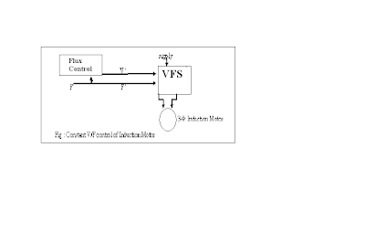
As shown in figure below, the motor is started through a Variable frequency – Variable Source (VFS) and a frequency command F ' is used to  change the control speed. This flux control block produces a voltage command V ' for VFS to maintain the ratio (V '/ F ') constant.
VFS can be a voltage source inverter or cyclo-converter.
A constant V/F control of Induction Motor is shown in figure:-


This variable frequency supply is generally obtained by the following inverters:-
i.)                  Voltage Source Inverter Drive
ii.)                Current Source Inverter Drive
iii.)              Cycloconverter controlled A.C. Drive.

i.)                  Voltage Source Inverter Drive :-  We know that the inverter converts a fixed voltage dc to a fixed ( or variable) a.c. voltage with variable frequency. Thus a voltage Source Inverter (VSI) allows a variable frequency supply to be obtained from dc supply.
The voltage source inverter feeding an induction motor is shown in figure:-

Each thyristor is to be fired for an angle 180˚. So, to maintain the air-gap flux of Induction Motor, the ratio of voltage and frequency must be kept constant. The output voltage is varied by varying d.c. input voltage. This adjustable d.c. voltage is obtained by using a controlled rectifier and inverter.

i.)                  Current Source Inverter Drive :- In this ac drive, the induction motor is controlled by using an current source inverter. This type of a.c. drive is known as Current source inverter drive as shown in figure :- 

Each thyristor are fired with a phase difference of 60˚ in sequence of their numbers i.e. SCR1, SCR2, SCR3, SCR4, SCR5, SCR6. Alarge inductance is connected in series to maintain a constant current. The diodes (D1- D6) and capacitors (C1-C6) provide commutation of thyristor (SCR1-SCR6).
The fundamental component of motor current (IL) is given by    IL  =  √ 6   .Id
                                                                                                                                                                          ∏
For a given speed, torque is controlled by varying dc link current (Id) and by changing the dc link voltage (Vd). Thus, dc voltage can be varied also by two arrangements.
First, when the ac supply is used , a controlled rectifier is connected between the supply and inverter and thus speed of induction motor can be controlled.
Another method is ,when dc supply is used, a chopper is connected between dc supply and inverter. Hence, in this way, the speed of induction motor is controlled.

i.)                   Cycloconverter controlled AC drive :- The Cyclo-converter allows variable frequency and voltage obtained from a fixed voltage and frequency of a.c. supply. Three- phase Cycloconverter drives are used to control the speed of both 3- phase induction motors and synchronous motor.
The Basic diagram of cycloconverter drives is shown in figure:-


However, the main disadvantage of cycloconverter based control drives is that the output frequency is one-third of the input frequency. Hence ,Cycloconverter are used to low speed induction motor drives.  


Wednesday, December 7, 2011

Moddes of Propagation of electromagnetic waves

# MODES OF PROPAGATION OF ELECTROMAGNETIC WAVES:→

The communication is done from one radiating antenna to receiving antenna with the help of propagation of radio waves in that region. So, some methods of propagation of radio waves are given below:-  
(i)                 Surface Wave Propagation.
(ii)               Sky Wave propagation
(iii)             Space Wave propagation.

(i.) SURFACE WAVE PROPAGATION:-   An electromagnetic wave that travels over the surface of the earth, this propagation of wave is known as surface wave propagation.
                         It is propagated by the charge induced in the earth when the waves move over earth surface. These charges move with wave and produce the current. But the earth offers a resistance to the flow of current, so energy is dissipated and the wave gets attenuated and propagates towards the earth’s surface .Surface wave used at frequencies as low as 15 KHz.

At high frequency, surface wave can not be used for long distance transmission because attenuation is more.
APPLICATIONS→ 1.) Surface wave used for ship to ship and ship to shore communication.
2.)    It is used for radio navigation and maritime mobile communication.
DISADVANTAGES→
(1)   Surface wave required a high power transmission.
(2)   These waves are limited to very low level and medium frequencies requiring large antennas.
(3)These losses in these waves may be increase or decrease with surface material.
ADVANTAGES→
(1)   Surface waves are not affected by changing weather condition.
(2)   At enough power it can be used to communicate between any two locations in the world.

(ii.) TROPOSCATTER PROPAGATION  or  SPACE WAVE PROPAGATION:-  In space wave propagation, the electromagnetic wave travels of earth’s atmosphere. Space waves may be both ground and reflected waves.
Direct wave travel in straight line between the transmitting and receiving antennas.
                      Space wave propagation with direct waves is called line-of-sight transmission (LOS). Therefore direct space wave is limited by the curvature of earth.
Ground reflected waves are the waves reflected by earth’s surface as they propagate between transmit and receive antenna.
The space wave propagation between two antenna is shown in figure:-
The field intensity at the receiver antenna depends upon the distance between the two  antennas. The curvature of earth presents horizon to space wave propagation called radio horizon.
                 The  refraction of wave is caused by the troposphere because of changes in its density, temperature ,water vapour content and relative conductivity,
        The region of radio horizon can be increased by elevating the transmit and receive antenna above the earth’s surface with tower or by placing them on the top of mountain or high building.
The space wave and radio horizon is shown in figure .
Let   d=distance to radio horizon(miles)
h=height of antenna above sea level.
         =>      d = √ 2h
        as        d = dt +dr
                        d = √ 2ht   +√ 2hr
where, dt = distance to radio horizon for transmit antenna
              dr = distance to radio horizon for receiving antenna
            ht = height of transmit antenna ,  &    hr = height of receiving antenna.

Duct Propagation:-  When the density of lower atmosphere is such that electromagnetic wave are trapped between lower atmosphere and earth’s surface then this type of propagation of wave is known as duct propagation.
The layer of atmosphere acts as duct, and hence the electromagnetic waves can propagate for a large distance around the curvature of earth with in this duct as shown in figure.
(iii) SKY WAVE PROPAGATION or  IONOSPHERIC PROPAGATION :- When the electromagnetic wave propagates in ionosphere region of earth’s atmosphere and these wave either reflected or reflected back to earth  by the ionosphere, then this  type of wave propagation is known as sky wave or ionospheric  propagation.
The Sky Wave Propagation is shown in fig.
The ionosphere located approximately 50km to 400km above the earth’s surface.
When a radio passes through ionosphere the electric field of the wave exerts a force on the free electrons causing then to vibrate.
These vibrating electrons decrease the current which is equivalent to reducing the dielectric constant.
By reducing the dielectric constant, the velocity of propagation is increases and hence the electromagnetic wave bent away from ionosphere toward the earth’s surface.

Basic Microwave Communication System/Link

Microwave communication system  [ECE]  --- by V.K. Mourya
# Basic Microwave Communication Link :-
                                                                       Microwave signal are used for communication over long distance continental or intercontinental. Microwave is the communication link which make the communication possible. The basic block diagram of microwave communication system is shown in figure.


Construction:
Antenna:- Mostly a parabolic refractor types of antenna are used which is used to transmit and receive the signal.
Circulator: A circulator is used to isolate transmitter with the receiver input and to couple transmitter to antenna and antenna to receiver input.
Protection Circuitry: It provides safety to the mixer from overloads.
Mixer (Receiver):  It has two outputs. One is the incoming signal and other is the signal from lower band pass filter (BPF).The mixer gives an IF signal of 70Mhz.
Band pass filter (BPF): It provides the necessary selectivity to the receiver and it prevents the interference.
IF amplifier and AGC:- It amplifies the signal up to a intermediate frequency of 70Mhz. and its gain is controlled through AGC (automatic gain control)
Amplitude limiter: As the signal is frequency modulated one so as amplitude limiter is used to avoid unwanted amplitude variations.
Mixer (Transmitter): It is used to convert IF frequency to transmitting microwave frequency band to pass through it and hence prevent interference.
POWER AMPLIFIER:-This amplifier amplifies the transmitted power from a repeater section in the range of 0.2W to 10W.
MICROWAVE SOURCE:- Klystron & Gunn Oscillators were used as microwave source. Now, V H F transistor crystal oscillators are used for microwave source.
POWER SPLITTER:- It divides the output power from a microwave source and feeds a large portion to the transmitter mixer, which converts it into transmitting microwave frequency.
SHIFT OSCILATOR:- It provides one of the inputs to the balanced mixer so that it produces 70MHz IF at the output of receiver mixer.
 
This microwave link communicates with 600 to 2700 channels per carrier. Thus the number of carriers in each direction can be four to twelve.


Saturday, December 3, 2011

<meta name="google-site-verification" content="ltXOT3H7VMT-KEKSO2IaqkPSLrCC0h5OSDbjFMyMVc0" />

Friday, November 18, 2011

Machine Drawing next Important questions[mech. engg.]

Important Definitions
31. Roughness width cut off :  The distance used to find the arithmetical average deviation is called the roughness width cut off.
32.Waviness :  It may be defined as the surface irregularities in the form of waves having larger wavelength.
33. Waviness height : It is the distance from the peak of the wave to its valley. It is measured in millimeters.
34. Waviness width : It is the spacing between the successive waves. It is measured in millimeters.

35.  Lay : Lay is the primary direction of the surface pattern prepared by machine tool marks.

36.  Flaws : They occur at random places on a machine component. These are cracks & scratches.

 37.  Ideal surface : It is a hypothetical perfect surface without any micro irregularity.

38.  Actual surface : It is defined as surface of a part which actually is received after machining surface.

39.  Nominal surface : A nominal surface is theoretical, geometrically perfect surface which is not to exist in the general practice.
40. Actual Profile :  It is the actual surface obtained by a manufacturing process.

41. Datum Profile : The profiles which passes through the lowest points of actual profile is called Datum profile.
42. Mean Profile : The profiles which passes  through the actual profile in such a way that the filled up areas between mean profile & actual profile is equal to the areas of voids between mean profile & actual  profile within sampling length.
43. What is reference profile?
Ans 43: The profile which passes through the highest points of actual profile is called reference profile.
44. What do you mean by peak to valley height?
Ans 44: It is the distance between reference profile & datum profile.
45. Define mean roughness index.
Ans45: It is the arithmetic mean of absolute values of heights of peaks or depth of valleys.
46. Define surface roughness number.
Ans 46: It is the average departure of machined surface over a sampling length which is generally taken as 800 microns.
47. Draw the basic symbols of surface roughness.


48. Define coupling.
Ans 48: It may be defined as the joining of two or more pieces of shafts in – order to obtain large length.
49. Where is Oldham’s Coupling best suited?
Ans 49: It is best suited to connect the shafts whose axes are parallel, but not in alignment.
50. Which  material is used for Oldham’s Coupling?
Ans 50: Shafts – Mild Steel
              Flanges & Disc – Cast Iron
              Keys – Mild Steel
51. Draw roughness symbols with values & grade numbers.