A.C. DRIVES [POWER ELECTRONICS] ---by V.K. Mourya
# Introduction : The electrical drive system which control the speed of A.C. motors is known as AC Drives.
So , according to types of motors and their industrial application there are two types of A.C. Drive.
i). Induction Motor drive
ii). Sunchronous Motor drive
Control Mechanism of Ac Drives:- Mostly, There are two types of control method of AC drives.
i). Variable Frequency A.C. Drives
ii). Constant V/F Operation
i). Variable Frequency A.C. Drives:- The speed of Induction Motor can be Calculated by given equation
Speed in RPM, Ns = 120 f
P
Where, f = frequency of AC supply, in Hz
P = Number of Poles in Stator Winding.
And the Voltage Equation of Induction motor is given by V = 4.44 KfΦNT
Where V = e.m.f. induced in stator, in volt.
Φ = air – gap flux in stator
NT = number of turns in stator winding.
As from above equations, It is clear that the Synchronous speed (Ns) is directly proportional to frequency (f)
i.e. Ns α f.
Thus the speed of motor can be controlled by varying supply frequency.
ii). Constant V/F operation:- As from Voltage Equation, V = 4.44 KfΦNT. If supply frequency (f) is changed, e.m.f induced in stator or voltage (v) also changed to maintain the same air – gap flux (Φ) below or above rated value, because the operation with air – gap flux (Φ) below or above rated value is not desirable.
So, to avoid saturation and to minimize losses, the motor is operated at rated air- gap flux by varying terminal voltage with frequency in the same ratio as to keep (V/f) ratio constant. This type of control is also known as “Constant volt per hertz”.
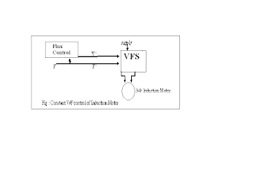
As shown in figure below, the motor is started through a Variable frequency – Variable Source (VFS) and a frequency command F ' is used to change the control speed. This flux control block produces a voltage command V ' for VFS to maintain the ratio (V '/ F ') constant.
VFS can be a voltage source inverter or cyclo-converter.
A constant V/F control of Induction Motor is shown in figure:-
This variable frequency supply is generally obtained by the following inverters:-
i.) Voltage Source Inverter Drive
ii.) Current Source Inverter Drive
iii.) Cycloconverter controlled A.C. Drive.
i.) Voltage Source Inverter Drive :- We know that the inverter converts a fixed voltage dc to a fixed ( or variable) a.c. voltage with variable frequency. Thus a voltage Source Inverter (VSI) allows a variable frequency supply to be obtained from dc supply.
The voltage source inverter feeding an induction motor is shown in figure:-
Each thyristor is to be fired for an angle 180˚. So, to maintain the air-gap flux of Induction Motor, the ratio of voltage and frequency must be kept constant. The output voltage is varied by varying d.c. input voltage. This adjustable d.c. voltage is obtained by using a controlled rectifier and inverter.
i.) Current Source Inverter Drive :- In this ac drive, the induction motor is controlled by using an current source inverter. This type of a.c. drive is known as Current source inverter drive as shown in figure :- 

The fundamental component of motor current (IL) is given by IL = √ 6 .Id
∏
For a given speed, torque is controlled by varying dc link current (Id) and by changing the dc link voltage (Vd). Thus, dc voltage can be varied also by two arrangements.
First, when the ac supply is used , a controlled rectifier is connected between the supply and inverter and thus speed of induction motor can be controlled.
Another method is ,when dc supply is used, a chopper is connected between dc supply and inverter. Hence, in this way, the speed of induction motor is controlled.
i.) Cycloconverter controlled AC drive :- The Cyclo-converter allows variable frequency and voltage obtained from a fixed voltage and frequency of a.c. supply. Three- phase Cycloconverter drives are used to control the speed of both 3- phase induction motors and synchronous motor.
The Basic diagram of cycloconverter drives is shown in figure:-
However, the main disadvantage of cycloconverter based control drives is that the output frequency is one-third of the input frequency. Hence ,Cycloconverter are used to low speed induction motor drives.


